
Autonomous Battery Powered iTiG Server
UNBOXING
The shipping crate is intended to be reused to allow safe storage of the batteries and iTiG server. Only take apart the shipping crates as outlined in the picture. Save all packaging material. Refer to the next two pictures to verify how far to break down the shipping crate.


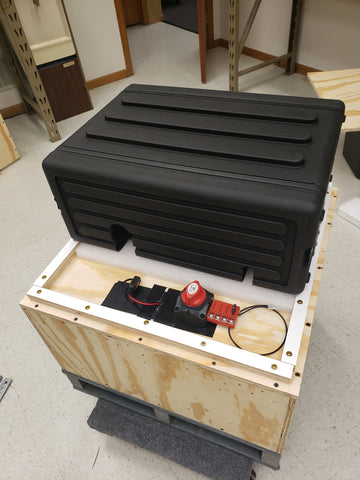
The bottom portion of the crate houses 2 automotive style AGM batteries. The Safety Data Sheet containing IATA regulations is available here. It is not necessary to open the bottom crate since the batteries are already wired to the main disconnect switch. Here is a picture of how the batteries are arranged. Again, there is no reason to open the bottom crate.

SENSOR INSTALLATION
Cut 2 pieces of silicone tape approximately 1.5" long and put under sensor (black silicone tape in picture, some silicone tape may be white). Use green tape to hold sensor and coil tight to glass on the inside of the IGU. Do not touch adhesive side of green tape with your fingers or it will loose it's ability to hold. Do not put tape over the area marked with a circle and 'x'. Ensure the sensor and coil are parallel with the glass.


TRANSMITTER COIL INSTALLATION
Apply the transmitter coil flat to the glass in line with the sensor coil. The side of the transmitter with the epoxy filled round shape should go towards the glass (smooth side away from the glass). Make sure it is aligned with the sensor coil to allow full power transfer through the glass. Apply some green tape to hold transmitter flat to the glass then use a few dabs of GOOP adhesive around the edge to provide a more permanent hold.

CONNECTING THE EXTENSION CABLES
Plug in the 20' extension cables to the back of the iTiG server until you feel the connector click.

Attach the small end to the transmitter coil then apply a small amount of GOOP adhesive to the outside to make a more permanent connection. Make a "service loop" with the wire so there is no tension on the connector. Apply some green tape to hold the wire to the glass. You may want to replace the green tape with some duct tape or use some GOOP for a more permanent connection.

SENSOR BLUETOOTH PAIRING
The iTiG sensors have already been paired with the iTiG servers. The red and blue stickers show which sensors have been paired to the corresponding server.
USING THE TIMER - MANUAL MODE
The clock on the timer and clock on the iTiG server are set to Coordinated Universal Time (UTC) which is a common base point when traversing different time zones.
Open the front and back black covers of the iTiG server then turn on the battery switch.
Push the AUTO/MANU button until the display shows that ON is selected. The ON mode will allow uninterrupted use of the server for setup. The POWER led will come on indicating the battery switch is turned on. The WORK led will come on indicating the timer switch is on.

USING THE TIMER - AUTO MODE
The clock on the timer and clock on the iTiG server are set to Coordinated Universal Time (UTC) which is a common base point when traversing different time zones.
Open the front and back black covers of the iTiG server then turn on the battery switch.
Push the AUTO/MANU button until the display shows that AUTO is selected. The AUTO mode will allow the timer to automatically control the power to the server. The POWER led will come on indicating the battery switch is turned on. The WORK led will come on only when the timer is in an active state.

AUTOMATIC OPERATION
This is the operational mode the battery timer needs to be in to automatically take measurements.
The automatic operating cycle goes like this:
1. With main battery disconnect switch on, the battery timer will fire every 4 hours. The clock on the battery timer is set to UTC time and the timers are preset as follows:
ON 00:00 OFF 00:09, ON 04:00 OFF 04:09, ON 08:00 OFF 08:09, ON 12:00 OFF 12:09, ON 16:00 OFF 16:09, ON 20:00 OFF 20:09. This cycle will repeat until the battery is turned off, the battery timer is set to manual or off, or the batteries completely die. The engineering calculations show the batteries will have more than enough amp hour capacity to power 13 sensors and iTiG server measuring every 4 hours in a 24 period for 3 weeks. It is not advised to change the timers.
2. When the battery timer switches on, the iTiG server and transmitter coils will power up.
3. The iTiG server then starts a 2 minute timer that will allow the transmitter coils which power the iTiG sensors to supply enough power to warm up the iTiG sensors.
4. After the 2 minute warmup period is over the iTiG sensors will start taking measurements, one after the other, in 22 second increments. There are 12 sensors paired with one iTiG server that will take cavity measurements and 1 sensor that is attached inside the iTiG server that will measure ambient conditions. The sensors are color coded to the iTiG server with either red or blue stickers.
5. There will be a short delay after which the iTiG server will power itself off and then after another delay the battery timer will power off.
6. The cycle repeats itself after another 4 hour delay.
MANUAL OPERATION
This is the operational mode the battery timer needs to be in to manually take measurements during setup and make adjustments to the iTiG server.
The manual operating mode bypasses the timers that have been set up in the battery timer. After putting the battery timer in manual mode the iTiG server needs to be paused. To pause the startup timer on the iTiG server you must click "Pause Startup Timer" on the bottom of the display by using either the trackpad on the keyboard or by touching the display. You will then see the "Startup Delay" timer stop counting down. Manual measurements can now be made by clicking on the "Measure" button as long as the sensor is powered by the transmitter. To scroll to another sensor, use the up or down arrows. The manual function is helpful to make sure the sensors are ready to go.
There is more information on the blog page:
https://fdrdesign.com/blogs/itig-server/using-the-software-version-r083118-0#manuallytakereadings
AUTO MODE CHECKLIST
1. Battery disconnect is set to ON
2. Battery timer is set to AUTO
3. Bluetooth dongle is plugged into iTiG server USB port and extends outside the shipping crate.
5. Transmitter coils are aligned with iTiG sensors and affixed to glass.
6. Transmitter coils are plugged into extension cables which connect to the iTiG server.
7. iTiG server covers are on and nothing is inside front cover that may touch the display.
8. Top portion of wooden crate is attached with foam on top of iTiG server to prevent bouncing.
ADDITIONAL NOTES
All AGM batteries were charged at FDR before shipping and should be recharged at your facility after testing and set up. Turn the battery disconnect switch off and plug the charger into the connector coming out of the lower crate. Leave connected until the full indicator light comes on. This may take a few hours even if the battery was not used much. The chargers go through a special cycle to make sure the batteries are fully charged.